System Maintenance occurs every Friday.
System Maintenance occurs every Friday.
Biased Resistive Contrast Imaging (BRCI) produces a logic map of a biased, static, low current CMOS integrated circuit. The images produced resemble a static voltage contrast map with the passivation removed and the topography subtracted as shown in Figure BRCIA. The BRIC technique does not require passivation removal. As the name suggests, BRCI is similar in concept and operation to the RCI technique with the IC biased, but a fully static CMOS IC will have all conductors at VSS or VDD when biased (at least at the gate level). The resistance difference between VSS and VDD then becomes a logic map when the IC is biased.
BRCI can eliminate or reduce the need for surface layer removal during failure site localization.
BRCI has limited application, i.e. low power static CMOS ICs, because the signals analyzed are small current perturbations (100's of pA) in the static supply current of an IC. If the supply current of an IC is larger than 250 mA, the BRIC perturbation current will be difficult or impossible to detect using commercially available current amplification equipment. This is because most commercial current amplification equipment that permits sample biasing through the current amplifier limit current supply to 250 uA. Even if a custom amplification system permits greater currents to be sourced by the IC under test through the current amplification system, the small BRCI currents are difficult to differentiate from the current noise for IC supply currents exceeding 250 uA.
BRCI, like many failure analysis techniques, can be most effectively used when analysis of a failing IC is compared to that of a nonfailing IC. BRCI images of the comparison IC and the failing IC are acquired with the same vectors. Differences between the two sets of images indicate areas for further analysis until the reason(s) for the differences are identified. The comparison IC should be considered "golden" in the sense that its BRIC images indicate the proper logic state for all the conductors on the IC.
Two basic methods can identify differences between BRCI images. The first is direct visual inspection. This simply means observing two BRIC images and trying to determine differences between the two. While this method has historically been performed regularly, its efficiency falls rapidly as the complexity of the IC (and therefore the image) increases. A second, preferred technique is to digitally acquire the two images, align them if necessary, and then subtract the two images from one another. An example of BRCI image subtraction is shown in Figure BRICB. Image subtraction makes analysis much easier because sources of contrast common to both images are "canceled" during subtraction and do not contribute to or complicate failure localization. The resultant difference image clearly highlights the conductors that are at different logic states on the IC. Note that image subtraction can also be effective without a comparison IC if only those conductors that change logic state are desired. This mitigates aligning the two images to be subtracted, since the images can be acquired from the same IC and the same field of view.
Digital image acquisition and subtraction of two BRCI images can greatly assist BRCI analysis. Image subtraction makes analysis much easier because sources of contrast common to both images are "canceled" during subtraction and do not contribute to or complicate failure localization. The resultant image clearly highlights the conductors that are at different logic states on the IC as seen in Figure BRICB. Image subtraction can be performed on two images of the failing IC, showing the differences between two logic states on conductors of the failing IC. Subtracting two or more difference images can further reduce the difference. In this case, the new difference image does not include the conductors that change states in both the original difference images.
Image subtraction can be performed on images from the failing IC and a comparison IC. The difference images produced will indicate the conductors that are in different logic states on the failing and comparison IC and may help isolate failure site(s). To take the difference between images from different ICs will require alignment of the two images before subtraction. This is a fairly common image processing function, assuming only linear operations (magnification, rotation, skew) are necessary to align the two images to be subtracted.
BRCI difference images make analysis easier by eliminating sources of contrast common to both images. Image subtraction eliminates sources of contrast common to both images; therefore, the common features do not contribute to or complicate failure localization. The resultant difference image clearly highlights the conductors at different logic states on the IC. Note that image subtraction can also be effective without a comparison IC if only those conductors that change logic state are desired. This mitigates aligning the two images to be subtracted, since the images can be acquired from the same IC and the same field of view.
Localization of the difference signal between two BRIC images is straight forward. If using image subtraction, simply look for the conductors (either dark or bright) that produce contrast in the difference images. The BRCI signal from conductors that are in the same logic state (same relative dark or bright contrast) will be "canceled" in the difference image.
If image subtraction is not used, the difference comparison can be employed, but the difference data extraction is complicated by the BRCI image contrast of all conductors on the IC. For even moderately complex ICs, this "brute force" data extraction becomes very difficult. Digital image acquisition and subtraction are highly recommended to localize difference signals for these situations.
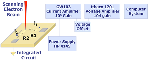
When biased, all conductors (at least at the gate level) of a properly functioning, fully static CMOS integrated circuit are connected to VDD or VSS, either directly or though one or more transistors. Under these conditions, the RCI data generated using VDD and VSS as the test nodes is binary for the integrated circuit. The BRCI image is generated by monitoring subtle shifts in the power supply current of the integrated circuit as an electron beam is scanned over the integrated circuit surface. These shifts occur as electrons are injected into the conductors of the integrated circuit. The amplification configuration shown in Figure BRCI2 operates in two stages. First, the power supply current is amplified and offset to eliminate the DC component of the integrated circuit's power supply current. The offset signal is then amplified to observe the fluctuations in IDD with electron beam position.
For BRCI and other FA tools, backtracing of a located failure refers to locating a failing conductor that is in an incorrect logic state ( for example a "1" when it should be "0") and determining why that conductor is in an incorrect state. This may be directly due to a failure (gate short, open metal, etc.) on the conductor under examination or because the upstream logic driving the node in question into an incorrect state is also in an incorrect logic state. If the incorrect logic state results from incorrect upstream driving logic, the upstream logic should be examined to determine why it is different from the expected result. This upstream or backtracing analysis is continued until the conductor drives correctly or the wrong logic state is located. The failure analysts then tries to locate and determine the failure mechanism producing this inconsistency.
BRCI images reveal the logic states of conductors on static CMOS ICs. Open metal conductors can be identified by an abrupt change in image contrast (i.e. logic state) along a conductor, as shown in Figure BRCIC. Failure mechanisms other than open conductors normally produce incorrect logic states (for example a "1" when it should be a "0") on the conductors examined by BRCI, but the failure mechanism producing the incorrect logic state needs additional analysis to be determined. With the exception of open conductors, BRCI imaging coupled with backtracing can identify the conductor directly associated with a given failure. Other analysis techniques are normally necessary to locate the failure site and determine the mechanism producing the failure.
BRCI is performed to measure the static logic levels of a low power CMOS device without removing the passivation or intervening metal layers. BRCI can also aid in the localization of open conductors in some cases, but the charge-induced voltage alteration (CIVA) technique is preferred over BRCI for open conductor localization. BRCI has limited application, i.e. low-power CMOS, because the signals analyzed are small current perturbations (100's of pA) in the static supply current of an IC. If the supply current of an IC is larger than 250 mA, the BRIC perturbation current will be difficult or impossible to detect using commercially available current amplification equipment. Most commercial current amplification equipment that permits sample biasing through the current amplifier limits current supply to 250 mA.
As with RCI, to obtain BRCI information, the primary electron beam energy is increased until the tip of the interaction volume intersects the buried conductors of interest (Figure 1).
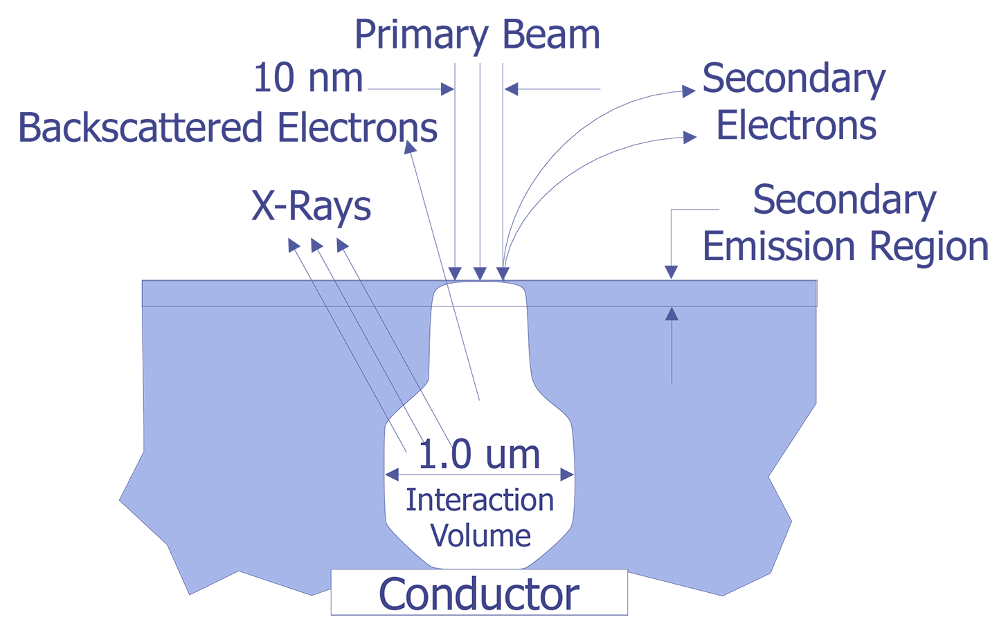
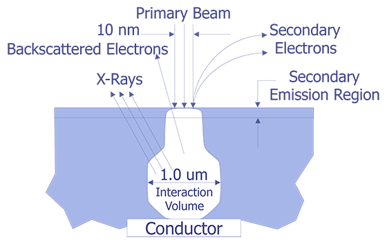
Under these conditions, a portion of the primary electron beam current will be injected into the conductor. Using an amplification configuration as shown in Figure 2, the currents injected by the primary electron beam will have a path out of the IC or test structure.
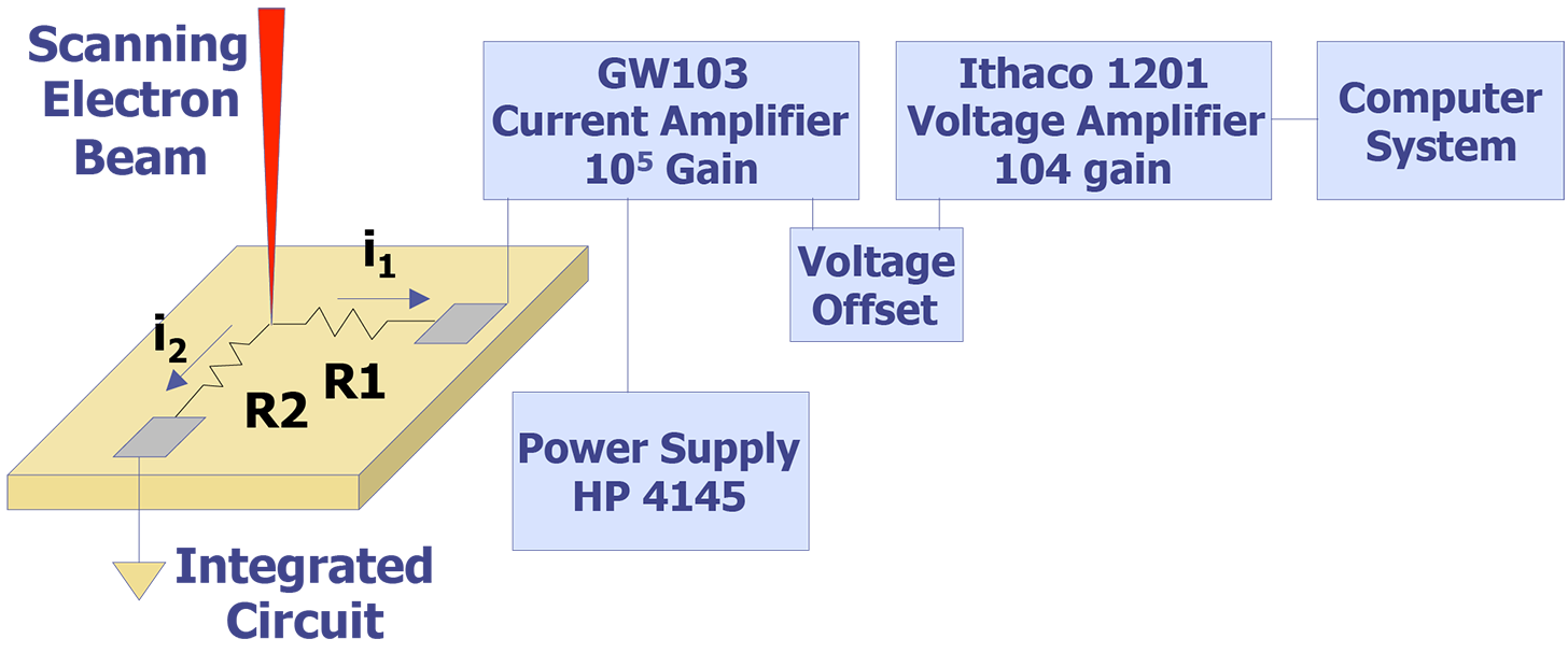
The relative resistance between the electron beam position on the sample and the test nodes will determine the direction and amplitude of current flow. The current, approximately 1 nA or less, is amplified and used to make a resistance map of the conductors. Using higher primary beam currents will increase the BRCI signal.
When biased, all conductors (at least at the gate level) of a properly functioning, fully static CMOS integrated circuit are connected to VDD or VSS, either directly or though one or more transistors. Under these conditions, the RCI data generated using VDD and VSS as the test nodes is binary for the integrated circuit. The BRCI image is generated by monitoring the subtle shifts in the power supply current of the integrated circuit as an electron beam, whose energy is selected as described above, is scanned over the integrated circuit surface. These shifts occur as electrons are injected into the conductors of the integrated circuit. The amplification configuration shown in Figure 2 operates in two stages. First, the power supply current is amplified and offset to eliminate the DC component of the integrated circuit's power supply current. The offset signal is then amplified to observe the fluctuations in IDD with electron beam position.
Since BRCI requires interaction between the primary electron beam and the conductors of interest, optically opaque layers may be "probed through" by increasing the primary electron beam energy. The following expression can be used for a rough estimate of the primary beam energy required to reach a given conductor:
R = 0.022 E1.65
where R is the distance below the surface and E is the primary electron beam energy.
Care must be taken not to exceed the minimum primary beam energy required for BRCI imaging. This is an important operating consideration for two reasons. First, if the primary electrons penetrate further than the conductors to diffused regions of the integrated circuit, then an electron beam induced current (EBIC) signal is generated from electron hole pair production that can be orders of magnitude greater than the BRCI signal. This will effectively "swamp out" the BRCI signal. Second, if the primary electrons penetrate to CMOS gate oxides, the threshold voltages of the exposed transistors can change by volts, making the integrated circuit inoperable.
BRCI should be performed if the static logic levels of buried conductors on low-power CMOS ICs (<250 mA) are required. BRCI should only be used after other, more benign failure analysis techniques have been applied. Even though BRCI can be used in a "non-destructive" fashion, producing very little irradiation damage to the oxide gates of an MOS IC, the possibility of altering IC operation still exists with primary electron beam energies greater than 1.0 kV. BRCI does have the advantage of being able to probe through passivation and metal layers. If the static logic levels of subsurface conductors are necessary, BRCI can be applied before layer removal, especially if there is reason to believe that layer removal will alter the nature of the logic level desired. Assuming that the IC can be biased and open conductors are indicated, the charge-induced voltage alteration (CIVA) technique is preferred over BRCI because of its higher selectivity, sensitivity, and larger IC operating current range. IC structures without transistors, such as thin-film resistance networks, are not suitable to CIVA; thus, RCI is the preferred method for this type of structure.
These requirements do limit the applicability of BRCI to a small subset of ICs, but the ability to probe through layers, such as overlaying metal-2, does make BRCI useful when appropriate ICs are used.